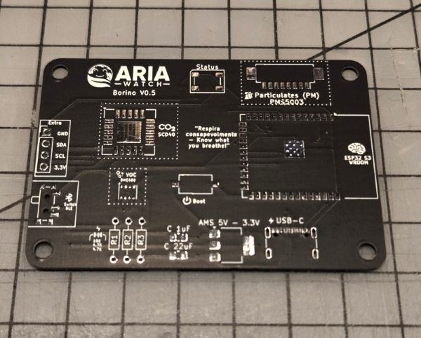
Borino PCB Assembly Guide
This guide describes the step-by-step process for assembling the Borino PCB, starting from receiving your custom board from the manufacturer.
If you wish to build the Borino device, it’s important to have prior experience with soldering, particularly surface-mount (SMD) techniques. Alternatively, the device can be prototyped using a breadboard and pre-soldered modules, but this approach isn’t covered in this guide.
Requirements
For the PCB build you are going to need at least the following:
Tools:
- Air solder (Hot air station)
- Soldering iron
- Flux
- Solder paste
- Solder
Components:
- 1 x USB Type C 16 Pin (USB4105)
- 1x 2.45mm 4 Pin Header
- 1x Molex 53261-0871 8 Pin
- 1x AMS1117 3.3v Regulator
- 1x 5050 RGB WS2812B LED
- 1x ESP32-S3 (With or with external antenna)
- 1x 1uF SMD 0805 Capacitor
- 1x 22uF SMD 0805 Capacitor
- 2x 4.7k Ohm 1/4W through hole resistors
- 1x 10k Ohm 1/4W through hole resistor
- 1x PMS5003
- 1x Bosch BME680
- 1x SCD40
All components can be sourced from popular suppliers such as Aliexpress.
Manufacturing the PCB
You can find the pcb design on our github right here: https://github.com/Aria-Watch/Aria-Watch-Borino-PCB
Feel free to choose with which manufacturer go, we suggest you JLCPCB.
Lets assemble!
So, lets get to the assembly process.
First of all, start with the bare minimum to test the ESP and power-data connections. We suggest you to follow the process as described here, but in the end you need to assemble all the components, feel free to do what you are comfortable with.
You can easily find where each components go as its marked on the PCB.
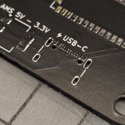
1- Type C
Place the necessary solder paste and proceed by soldering the Type-C connector using hot air:
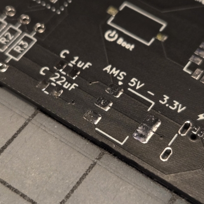
2- AMS1117 3.3V and capacitors
You can proceed in order, to solder the capacitors and the AMS power regulator, for this one you can use a soldering iron as the capacitors and the pads are big enought:
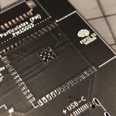
3- ESP32-S3
Last for now, solder the ESP32-S3 Package. If you are brave enough you can proceed by soldering each pin with the soldering iron, but it's recommended to do it with the hot-air station:
At this point we soldered al the basic components to test that the USB power and data lines are correctly working:
- Try to connect the USB Type-C to a computer.
- Verify that a new COM device it's showing in the device manager.
- If you see the device connecting/disconnecting it's all right, the micropython firmware it's missing so it's expected.
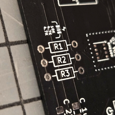
4- Resistors
You can now proceed to solder the rest of the components, the resistors are labeled on the PCB, for this we recommend using the soldering iron:
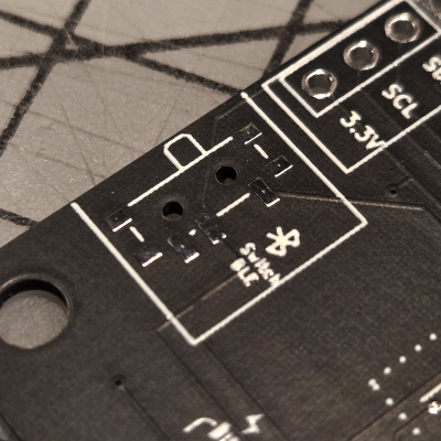
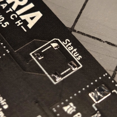
5- BLE Switch
As for the resistors, you can solder this tiny switch with the soldering iron:
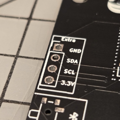
6- Headers
In the same area, you will find the place for the I2C Headers, proceed to solder those if you want to expand the board with some other custom sensors.
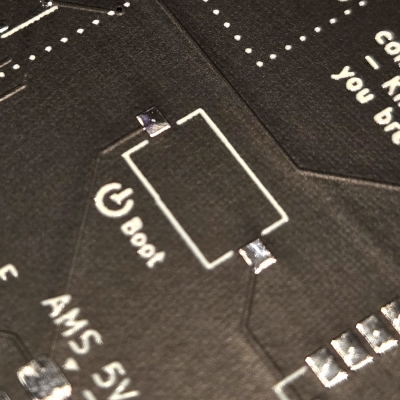
7- BOOT button
With the soldering iron also proceed to solder the button needed to choose the boot mode for the ESP32:
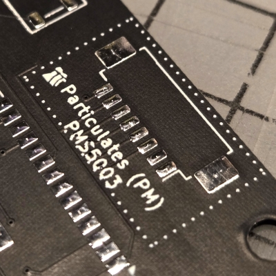
8- PM Sensor header (Molex 53261-0871 8 Pin)
Place some solder paste where needed and proceed to solder using hot air the Molex connector needed for the PM sensor:
9- 5050 LED
Keeping the hot air in hand, proceed to place some solder paste on the LED pads, and solder it:
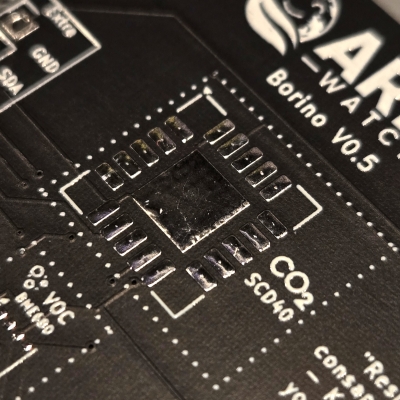
10- CO2 Sensor
Now for the section that needs the most attention, sensors! Be careful while soldering these as too much heat can damage them, apply the barely needed solder paste and proceed starting from the CO2 sensor:
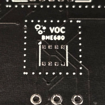
11- VOC Sensor
Last, the hardest one to solder with the heat gun, the Bosh VOC sensor, apply just a bit of solder paste on the pads and proceed to put in place the little guy without losing it on the desk:
Final Steps: Firmware Installation
Refer to the firmware README for connection and flashing instructions: https://github.com/Aria-Watch/Aria-Watch-Firmware
Tips
- Follow component orientation and polarity as marked.
- Review each solder joint with a magnifier; cold or bridged joints commonly cause assembly issues.
- Ensure your work area is ESD-safe, especially when handling sensitive ICs.
- Include test and inspection steps after initial assembly for troubleshooting